Release Notes (v.1.2)
Physics
General
3D Layout
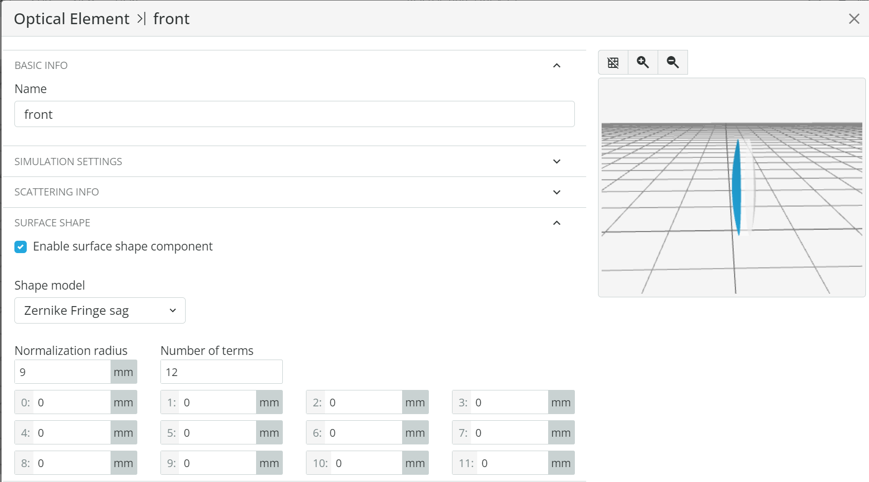
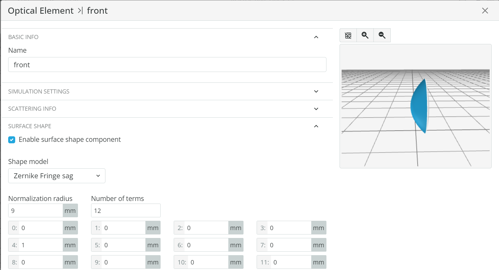
Zernike Fringe Sag can be added to every optical surface by clicking on the Element Settings button in the right toolbar. Then select Optical Surfaces. Select the front or back and then Surface Shape > Enable Surface Shape Component > Zernike Fringe sag. Specify the normalization radius in mm and the number of Zernike terms. The 3D model of the lens is updated immediately.
For polychromatic light sources there are two options for the number of analysis rays: total (as in release 1.1) and per wavelength (new). For example, setting 10^6 rays will trace 10^6 rays per wavelength in “per wavelength mode”. If seven discrete wavelengths are used then a total of 7*10^6 rays will be traced. In “total” mode, a total of 10^6 rays will be traced, and the number of rays per wavelength is set according to the wavelength weight. If all the weights are equal to 1, the quantity will be distributed equally and the total will be 10^6. For a monochromatic source, switching between modes won’t make any difference.
To use this feature: click the Light Source settings button and then Number of rays: total/per wavelength.
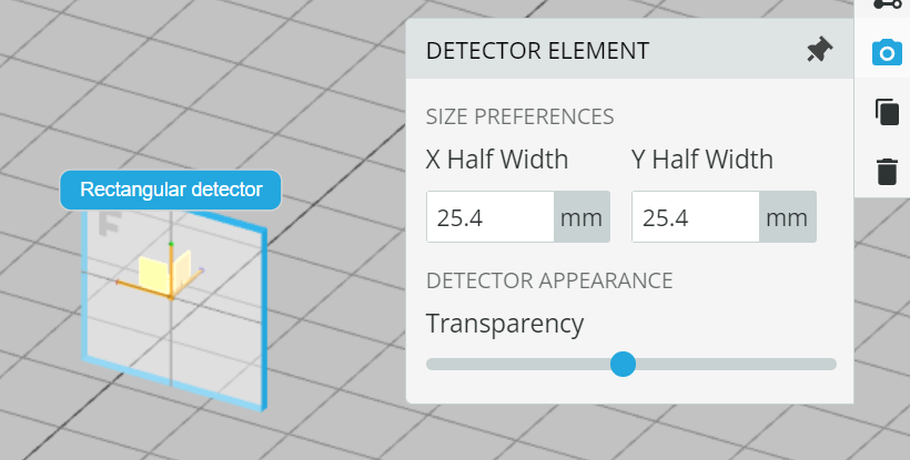
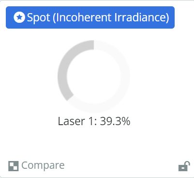
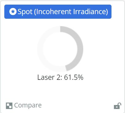
In order to make the use of detectors more intuitive and user-friendly, we improved three appearance settings:
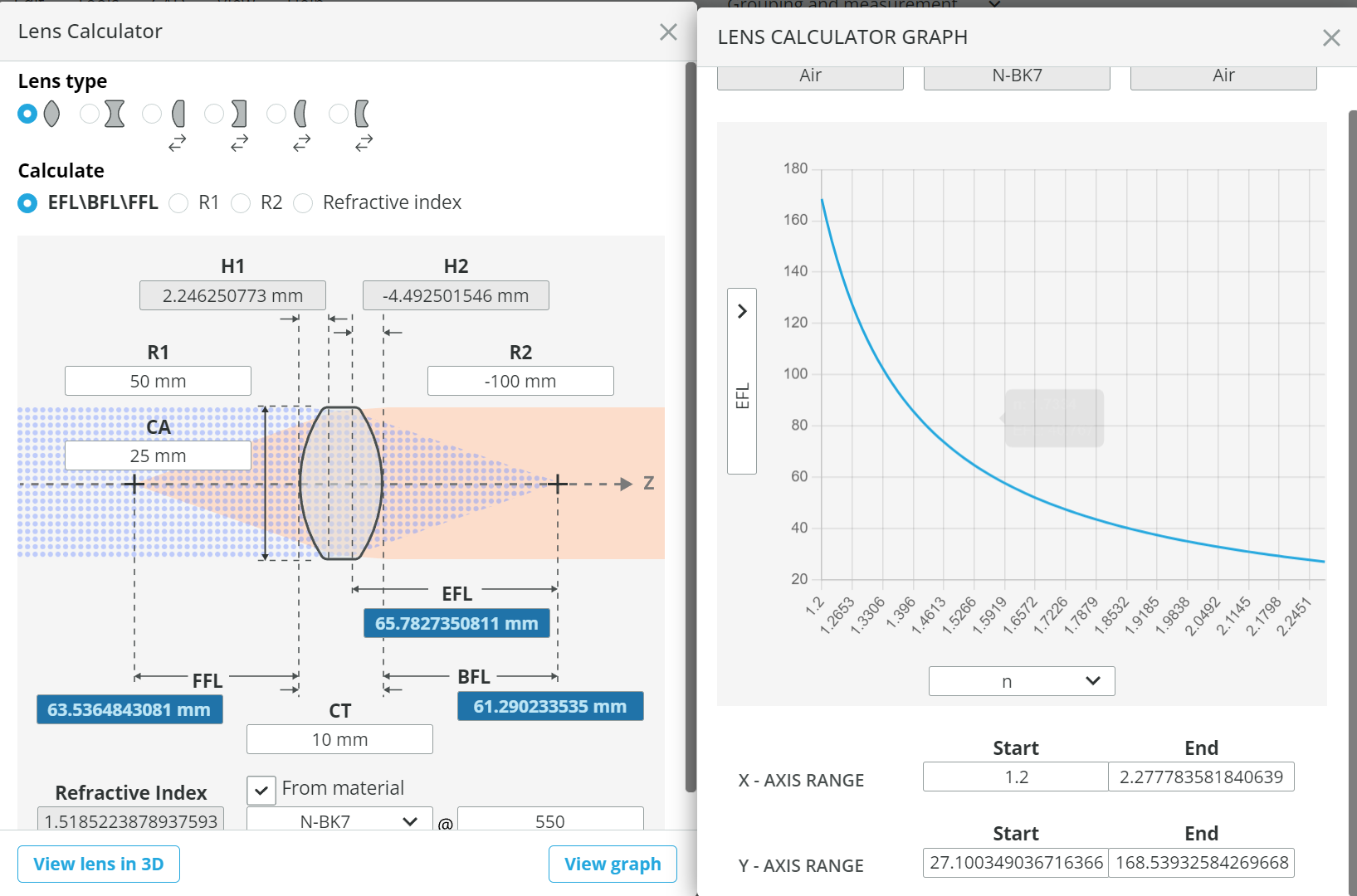
A user-friendly calculator for various lens types and relations has been added, i.e. EFL vs. R1/R2 for a given refractive index and refractive index vs. EFL, for a given R1/R2. In a universal chart you can select the x and y axes, as well as the range. To use this feature, select Tools > Lens calculator.
You can upload any step file (up to 10 MB for basic, up to 30 MB for premium license holders) to the layout. In a few weeks’ time it will be upgraded with optical functionality, i.e. step file elements will have optical properties, such as refractive index and transmission coefficient. To import a step file, select File > Import CAD.
To estimate a simulation’s run time, there is now an analysis progress bar in the Analysis portal.
If you want your simulation to run twice as fast, click the Turbo button in the analysis portal. It changes color to green. You can now click the Run analysis button.
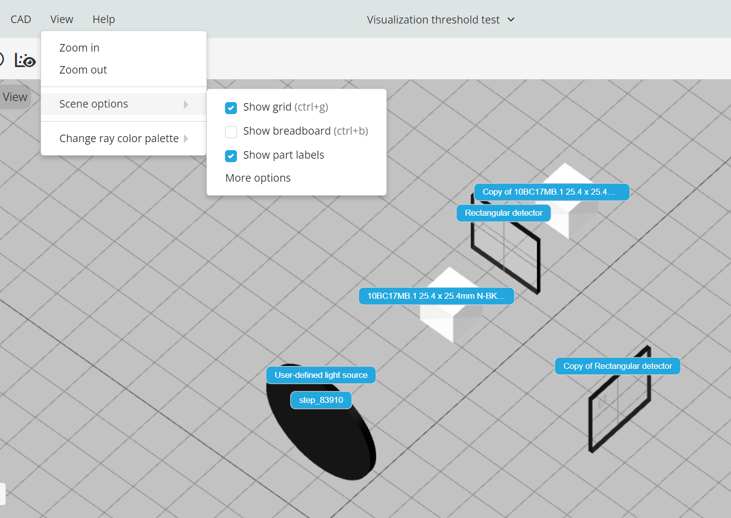
Each part name (label) can now be displayed in the layout. To use this feature, select View > Scene options > Show part labels.
Previously, settings were global and now they can be customized for each setup. Under the Design and Simulation Tool settings there are two sections: Global and setup related. Each new setup will be created with global settings, which can then be changed for the specific setup, without affecting the global settings. To use this feature, press your account name in the top right corner and then select User Settings.
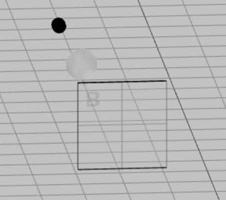
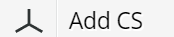
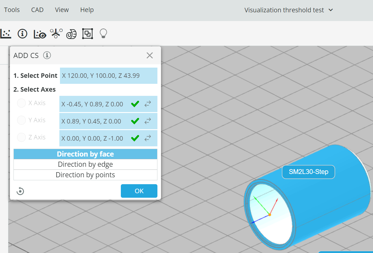
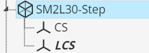
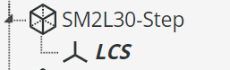
A new coordinate system (CS) can be added to any location on the layout, and a CS can also be created and applied to a specific location and orientation of a step object. To create a new CS, place the cursor on the object (on the layout or outliner) and select . Follow the instructions to create a new CS. It will then appear in the object outliner.
Before After
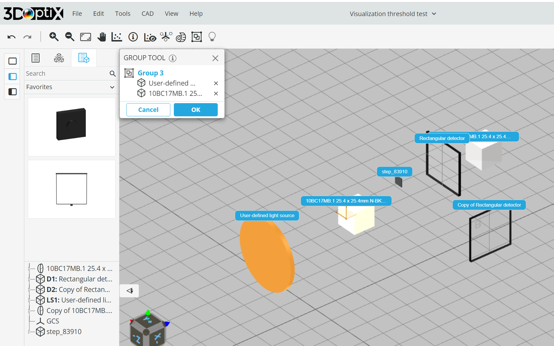
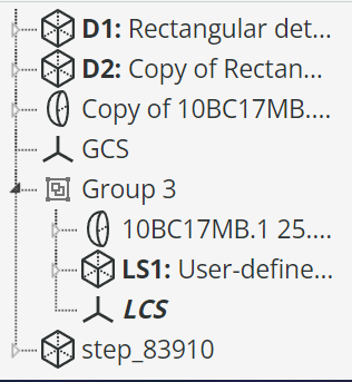
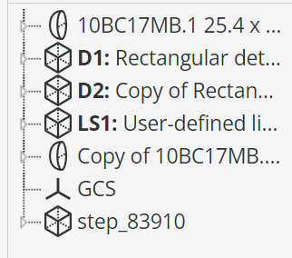
Elements now can be grouped. Press the group tool icon and follow the instructions. A group entity will be added to the outliner, where its elements can be edited, the group name can be changed, or the elements can be ungrouped.
Before grouping after grouping
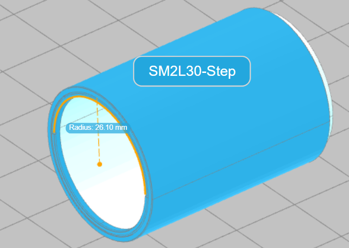
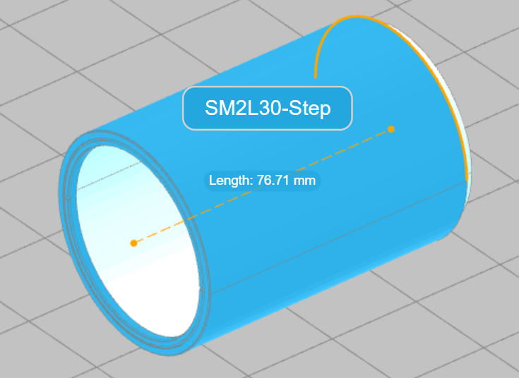
Basic length, distance and angle measurements have been added to CAD objects (both objects in the 3DOptix library and imported step files). To use this feature, press the Measurement Tool icon and select your preferred units – mm/inch and deg/rad. When you click the selectable edges and surfaces, the relevant measurements are displayed.